- 您现在的位置:买卖IC网 > Sheet目录2001 > ISL12022MIBZR5421 (Intersil)IC RTC/CALENDAR TEMP SNSR 20SOIC
ISL12022MR5421
17
FN7576.3
June 7, 2012
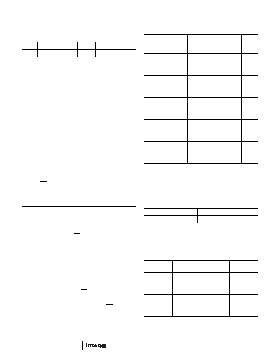
Interrupt Control Register (INT)
AUTOMATIC RESET BIT (ARST)
This bit enables/disables the automatic reset of the ALM, LVDD,
LBAT85, and LBAT75 status bits only. When ARST bit is set to “1”,
these status bits are reset to “0” after a valid read of the
respective status register (with a valid STOP condition). When the
ARST is cleared to “0”, the user must manually reset the ALM,
LVDD, LBAT85, and LBAT75 bits.
WRITE RTC ENABLE BIT (WRTC)
The WRTC bit enables or disables write capability into the RTC
Timing Registers. The factory default setting of this bit is “0”.
Upon initialization or power-up, the WRTC must be set to “1” to
enable the RTC. Upon the completion of a valid write (STOP), the
RTC starts counting. The RTC internal 1Hz signal is synchronized
to the STOP condition during a valid write cycle.
INTERRUPT/ALARM MODE BIT (IM)
This bit enables/disables the interrupt mode of the alarm
function. When the IM bit is set to “1”, the alarm will operate in
the interrupt mode, where an active low pulse width of 250ms
will appear at the IRQ/FOUT pin when the RTC is triggered by the
alarm, as defined by the alarm registers (0Ch to 11h). When the
IM bit is cleared to “0”, the alarm will operate in standard mode,
where the IRQ/FOUT pin will be set low until the ALM status bit is
cleared to “0”.
FREQUENCY OUTPUT AND INTERRUPT BIT (FOBATB)
This bit enables/disables the IRQ/FOUT pin during battery
backup mode (i.e. VBAT power source active). When the FOBATB
is set to “1”, the IRQ/FOUT pin is disabled during battery backup
mode. This means that both the frequency output and alarm
output functions are disabled. When the FOBATB is cleared to
“0”, the IRQ/FOUT pin is enabled during battery backup mode.
Note that the open drain IRQ/FOUT pin will need a pull-up to the
battery voltage to operate in battery backup mode.
FREQUENCY OUT CONTROL BITS (FO <3:0>)
These bits enable/disable the frequency output function and
frequency selection. Default for the ISL12022MR5421 is FO<3:0>
= 1h, or 32.768kHz output (FOUT is ON). When the frequency mode
is enabled, it will override the alarm mode at the IRQ/FOUT pin.
Power Supply Control Register (PWR_VDD)
CLEAR TIME STAMP BIT (CLRTS)
This bit clears Time Stamp VDD to Battery (TSV2B) and Time
Stamp Battery to VDD Registers (TSB2V). The default setting is 0
(CLRTS = 0) and the Enabled setting is 1 (CLRTS = 1).
VDD BROWNOUT TRIP VOLTAGE BITS (VDDTRIP<2:0>)
These bits set the trip level for the VDD alarm, indicating that VDD
has dropped below a preset level. In this event, the LVDD bit in
the Status Register is set to “1”. See Table 7.
TABLE 3. INTERRUPT CONTROL REGISTER (INT)
ADDR
7
6
5
4
321
0
08h
ARST
WRTC
IM
FOBATB
FO3 FO2 FO1 FO0
TABLE 4. IM REGISTER
IM BIT
INTERRUPT/ALARM FREQUENCY
0
Single Time Event Set By Alarm
1
Repetitive/Recurring Time Event Set By Alarm
TABLE 5. FREQUENCY SELECTION OF IRQ/FOUT PIN
FREQUENCYFOU
T
UNITS
FO3
FO2
FO1
FO0
0Hz
0
32768
Hz
0
1
4096
Hz
0
1
0
1024
Hz
0
1
64
Hz
0
1
0
32
Hz
0
1
0
1
16
Hz
0
1
0
8Hz
0
1
4Hz
1
0
2Hz
1
0
1
1Hz
1
0
1
0
1/2
Hz
1
0
1
1/4
Hz
1
0
1/8
Hz
1
0
1
1/16
Hz
1
0
1/32
Hz
1
TABLE 6. CLRTS REGISTER
ADDR
7
6
5
4
3
2
1
0
09h
CLRTS
0
VDDTrip2 VDDTrip1 VDDTrip0
TABLE 7. VDD TRIP LEVELS
VDDTrip2
VDDTrip1
VDDTrip0
TRIP VOLTAGE
(V)
00
0
2.295
00
1
2.550
01
0
2.805
01
1
3.060
10
0
4.250
10
1
4.675
发布紧急采购,3分钟左右您将得到回复。
相关PDF资料
ISL12023IVZ
IC RTC/CLDR TEMP SNSR 14-TSSOP
ISL12024IRTCZ
IC RTC/CALENDER 64BIT 8-TDFN
ISL12024IVZ
IC RTC/CALENDAR EEPROM 8-TSSOP
ISL12025IVZ
IC RTC/CALENDAR EEPROM 8-TSSOP
ISL12026IBZ-T7A
IC RTC/CALENDAR EEPROM 8SOIC
ISL12027IV27AZ
IC RTC/CALENDAR EEPROM 8-TSSOP
ISL12028IVZ
IC RTC/CALENDAR EEPROM 14-TSSOP
ISL12029IVZ
IC RTC/CALENDAR EEPROM 14-TSSOP
相关代理商/技术参数
ISL12022MIBZ-T
功能描述:实时时钟 REAL TIME CLK & TEMP COMPENSATED CRYSTAL RoHS:否 制造商:Microchip Technology 功能:Clock, Calendar. Alarm RTC 总线接口:I2C 日期格式:DW:DM:M:Y 时间格式:HH:MM:SS RTC 存储容量:64 B 电源电压-最大:5.5 V 电源电压-最小:1.8 V 最大工作温度:+ 85 C 最小工作温度: 安装风格:Through Hole 封装 / 箱体:PDIP-8 封装:Tube
ISL12022MIBZ-T7A
功能描述:IC RTC/CALENDAR TEMP SNSR 20SOIC RoHS:否 类别:集成电路 (IC) >> 时钟/计时 - 实时时钟 系列:- 产品培训模块:Obsolescence Mitigation Program 标准包装:1 系列:- 类型:时钟/日历 特点:警报器,闰年,SRAM 存储容量:- 时间格式:HH:MM:SS(12/24 小时) 数据格式:YY-MM-DD-dd 接口:SPI 电源电压:2 V ~ 5.5 V 电压 - 电源,电池:- 工作温度:-40°C ~ 85°C 安装类型:表面贴装 封装/外壳:8-WDFN 裸露焊盘 供应商设备封装:8-TDFN EP 包装:管件
ISL12022MIBZ-TR5421
功能描述:实时时钟 REAL TIME CLK W/MFK IMPROVED ESD AIR RoHS:否 制造商:Microchip Technology 功能:Clock, Calendar. Alarm RTC 总线接口:I2C 日期格式:DW:DM:M:Y 时间格式:HH:MM:SS RTC 存储容量:64 B 电源电压-最大:5.5 V 电源电压-最小:1.8 V 最大工作温度:+ 85 C 最小工作温度: 安装风格:Through Hole 封装 / 箱体:PDIP-8 封装:Tube
ISL12022MR5421
制造商:INTERSIL 制造商全称:Intersil Corporation 功能描述:Low Power RTC with Battery Backed SRAM, Integrated 5ppm
ISL12022M-R5421
制造商:INTERSIL 制造商全称:Intersil Corporation 功能描述:High-Accuracy RTC Modules, Feature-Rich RTCs
ISL12023
制造商:INTERSIL 制造商全称:Intersil Corporation 功能描述:Low Power RTC with Battery-Backed SRAM and Embedded Temp Compensation ±5ppm with Auto Daylight Saving
ISL12023IVZ
功能描述:实时时钟 REAL TIME CLK/CLNDR W/TEMP COM 14 L RoHS:否 制造商:Microchip Technology 功能:Clock, Calendar. Alarm RTC 总线接口:I2C 日期格式:DW:DM:M:Y 时间格式:HH:MM:SS RTC 存储容量:64 B 电源电压-最大:5.5 V 电源电压-最小:1.8 V 最大工作温度:+ 85 C 最小工作温度: 安装风格:Through Hole 封装 / 箱体:PDIP-8 封装:Tube
ISL12023IVZ-T
功能描述:实时时钟 REAL TIME CLK/CLNDR W/TEMP COM 14 L RoHS:否 制造商:Microchip Technology 功能:Clock, Calendar. Alarm RTC 总线接口:I2C 日期格式:DW:DM:M:Y 时间格式:HH:MM:SS RTC 存储容量:64 B 电源电压-最大:5.5 V 电源电压-最小:1.8 V 最大工作温度:+ 85 C 最小工作温度: 安装风格:Through Hole 封装 / 箱体:PDIP-8 封装:Tube